
3D & Product Design
Mechanical design that respects the PCB, connectors, battery, buttons, antennas, airflow, assembly and the realities of prototyping.
Engineering outputs prepared for the next real step.
Deliverables are scoped around your project rather than forced into a fixed package.
- Fusion 360 source model as scoped
- STEP and STL exports
- Enclosure top/bottom or multi-part assembly
- PCB standoffs, connector openings and fastening features
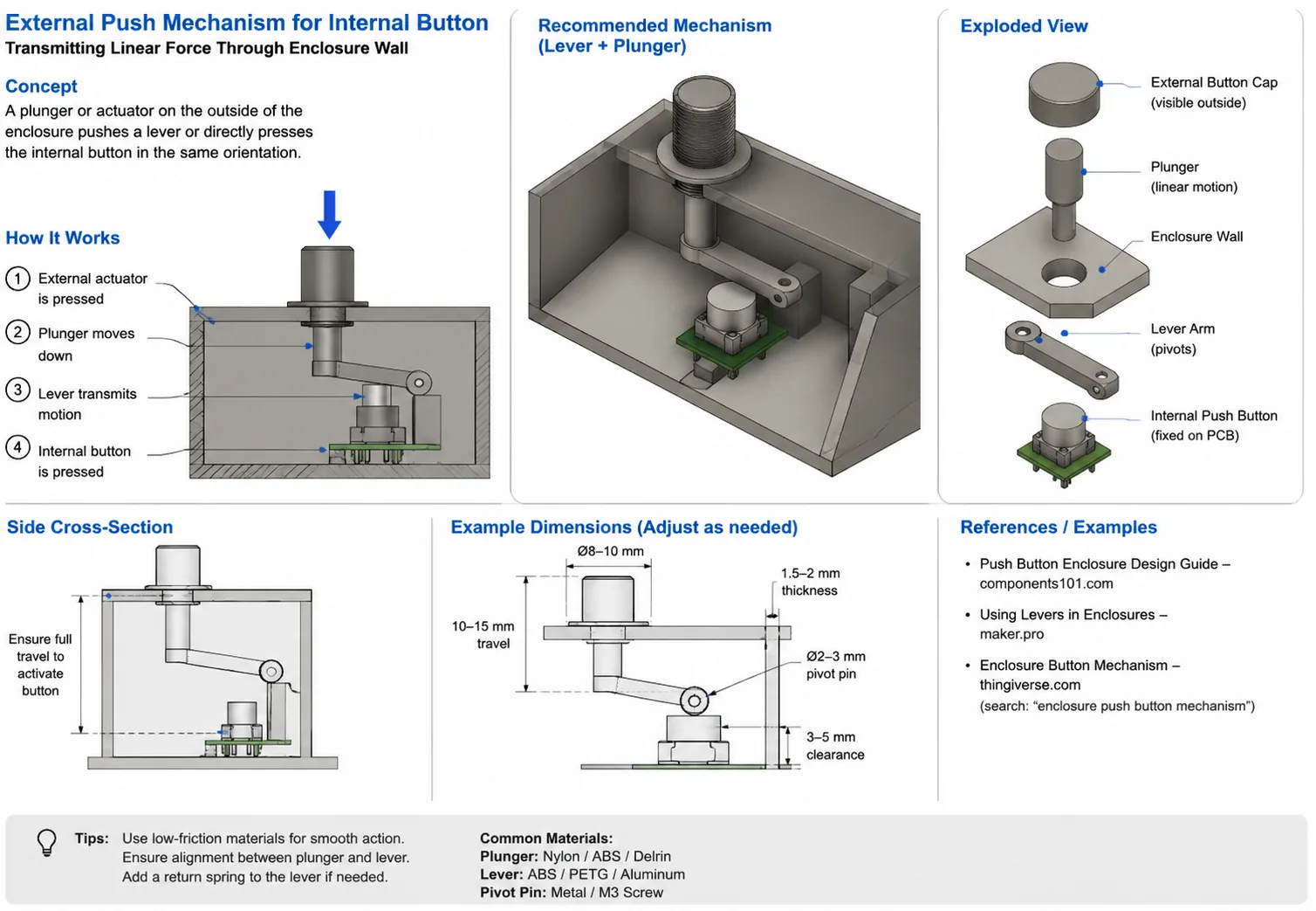
- Button/plunger and user-interface mechanisms
- Battery, vent and antenna-space planning
- Prototype-ready dimensions and assembly notes
- Revision support after first print or fit check
Technical depth where the project needs it.
PCB integration
Use board outline, mounting holes, connector positions and keepouts to drive the enclosure rather than guessing.
Mechanical interfaces
Design buttons, plungers, switches, ports, battery retention, vents and assembly features.
Prototype DFM
Wall thickness, tolerances, screw bosses, print direction and serviceability considered for rapid prototypes.
Handoff formats
Provide editable CAD plus STEP/STL outputs suitable for review, printing or supplier communication.
How this work is approached.
- 01
Lock the electronics envelope
Confirm PCB dimensions, connectors, battery, antenna and moving/mechanical elements.
- 02
Develop the enclosure
Build the assembly around access, ergonomics, fastening and manufacturing constraints.
- 03
Fit-check digitally
Review clearances, travel, interference, opening sizes and assembly sequence.
- 04
Prototype & iterate
Use the first physical print/fit check to capture tolerances before finalizing production intent.
For reverse engineering or third-party hardware, clients are expected to own the hardware or have authorization to analyze, repair or redesign it. Revorix does not accept work intended to violate third-party intellectual-property rights.